
Custom steel beam welding for applications like: engineered metal buildings, pre-engineered steel buildings, shipyards, semi truck trailers / tractor truck beds, bridges, and platforms.
You can now manufacture custom beams continuously with minimum delays for changing beam sizes or shapes. The PHI Automatic Beam Welder gives your operation higher productivity, on both straight and tapered beams. It automatically welds both flanges of the beam at once, delivering the penetration you need on up to 1/2″ web and 1 1/2″ flange — all in one operation, one pass, and from one side. The PHI system produces a fillet weld between the web and flange. Welds are uniform and of the quality demanded by construction codes.
Seam Welder
 The seam welder is used to join separate web sections with a 100% welded seam and to fabricate long webs from short sections or to join sections of different thickness.
The two pieces to be joined are aligned against an edge guide and clamped in position by means of air cylinders. The grooved copper back-up plate is brought to seam tightly against the lower side of the joint. The welding head travels along the joint and welds it by single-wire submerged arc.
Clamps are released and web is conveyed to the tacking fixture. Welding equipment consists of welding head with flux hopper, travel carriage, controls and a 1,000 Amp power source.
A flux recovery system is provided to dispense and recover welding flux. The Seam Welder Hydraulic Power Unit and Electric Controls are also used to drive the conveyors at entrance and exit of the Seam Welder.
Tacking Fixture
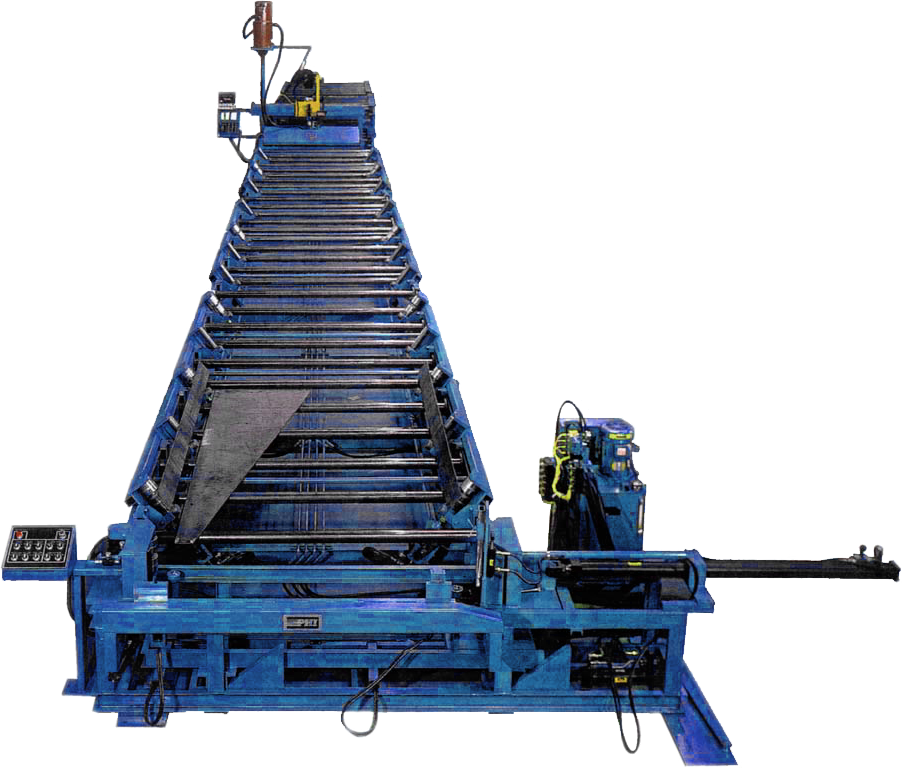 The tacking fixture is used to assemble the beam prior to the Main Welder. The web and flanges are brought in from the seam welder and flange storage racks respectively, transported to the tacking fixture and positioned prior to tacking the leading edge of the beam. Loading of the flanges on the conveyors can be done manually by an operator or automatically, using PHI’s flange-loading Gantry.
The two flanges are placed on the conveyor section on opposite sides of the web, rotated into the vertical position and held by magnetic guide rollers. The three pieces are advanced into position against a retractable stop and hydraulically clamped in their proper relative position. The operator manually tack welds them together. Clamps are released, and the tack-welded beam is conveyed to the welder. After initial adjustment of clamp positions for the first beam, the operator controls all material movement from the control panel for all subsequent beams of the same size.
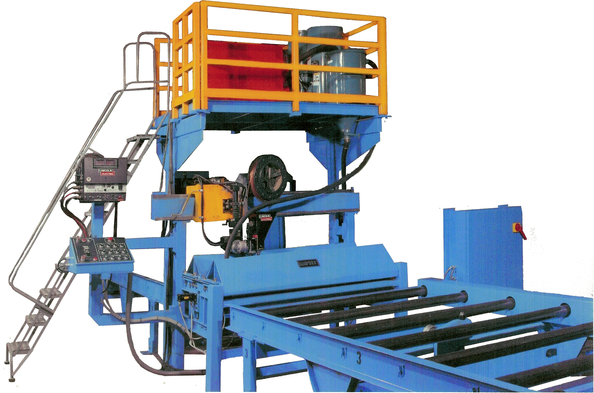
Electric Controls
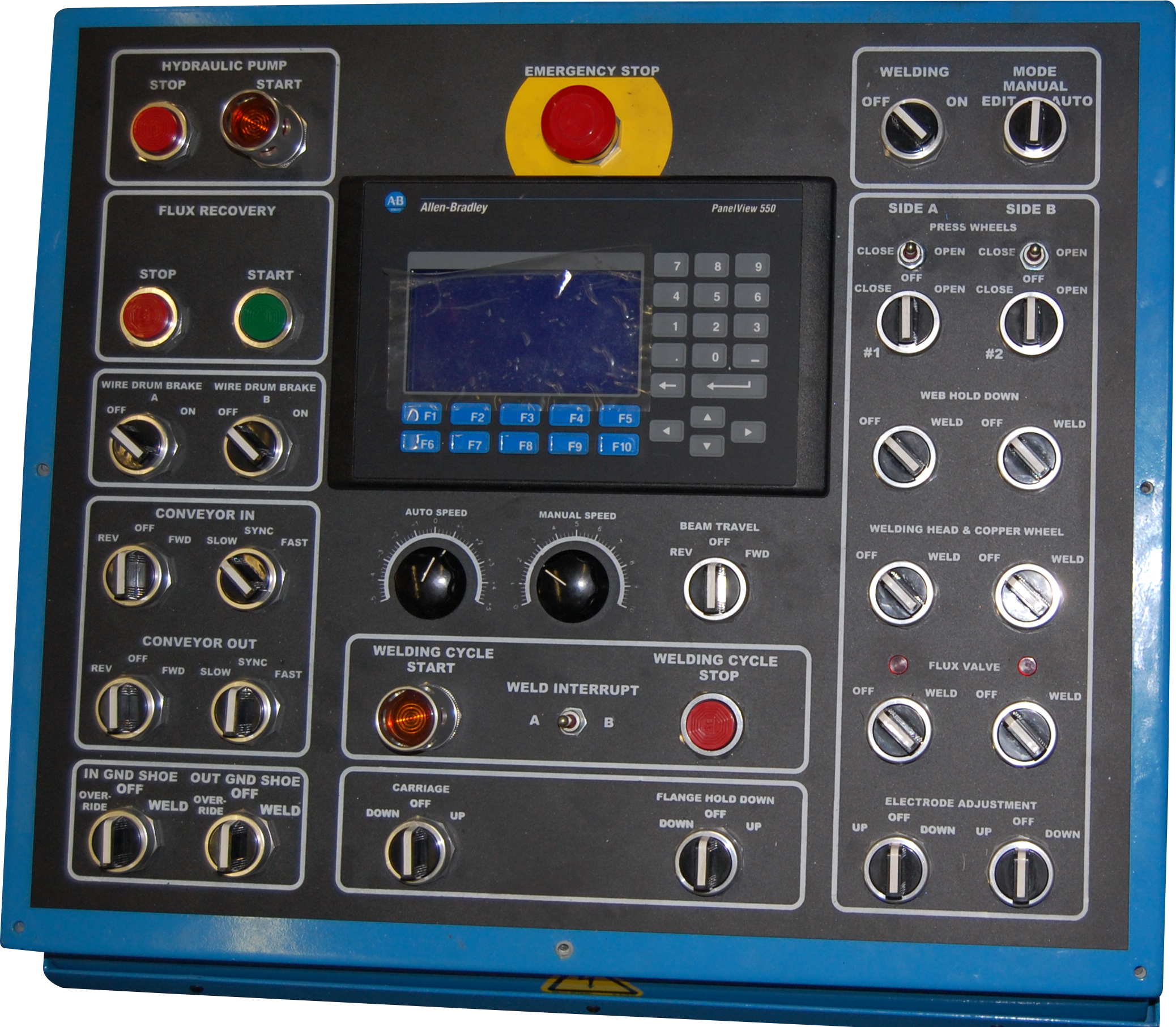 The Electrical Control Panel on the Main Welder provides maximum system control flexibility. The Welder can be operated in either Manual Mode or Automatic Mode.
In Manual Mode, the sequence of operations is achieved by using individual controls located on the control panel. Welding parameters also are set individually on each welding head controller.
In Automatic Mode, the PLC control increases “arc-on” time by eliminating manual operations.
Using the “IN” conveyor, operator brings the beam to the starting position, chooses one of the preset welding programs (welding speed, wire speed and voltage), and pushes the “START” button.
Total sequence of operations, including movement of the beam with welding speed, positioning of the welding heads, start and stop of the welding process on stationery and moveable sides, activation of web holding, copper back-up assemblies and pressure cylinders, and STOP of the operation will be accomplished automatically.
The PLC provides the accuracy, reliability, versatility quality, and quick change of the parameters for different welding applications.
The interface between operator and machine is through an Allen Bradley Panel View, which has been programmed by PHI to display all parameters of a welding program, and to display on different screens input/output status for troubleshooting and diagnostics.
Programming of welding parameters for different beam sections is also accomplished through the panel view screens.
Conveyors
 The Seam Welder, Tacking Fixture and Automatic Welder are interconnected by means of a Conveyor System, to form a complete production line that allows continuous beam production.
Conveyors are located at the entrance and exit of Seam Welder, Tacking Fixture and Automatic Welder, and are hydraulically operated. The controls at each of these stations determine the movement, direction, and speed of the adjacent conveyors.
A typical layout system includes a total of 18 conveyor sections. Six are motorized, driving the rollers by means of sprockets and chains. Ten are driven, connected by chains to adjacent motorized sections. Two are idle. Each conveyor section measures 10’ in length, 94” width and 30” height. Rollers are heavy duty designed for handling heavy steel plates and are spaced on 22” centers.
Load capacity for each conveyor section is approximately 4,000 lbs. Conveyor speeds are synchronized with welder input speeds to minimize conveyor wear resulting from friction between the turning roller and slower-moving beam at the welder entrance.
Machine Capacity
| Machine Capacity | |
|---|---|
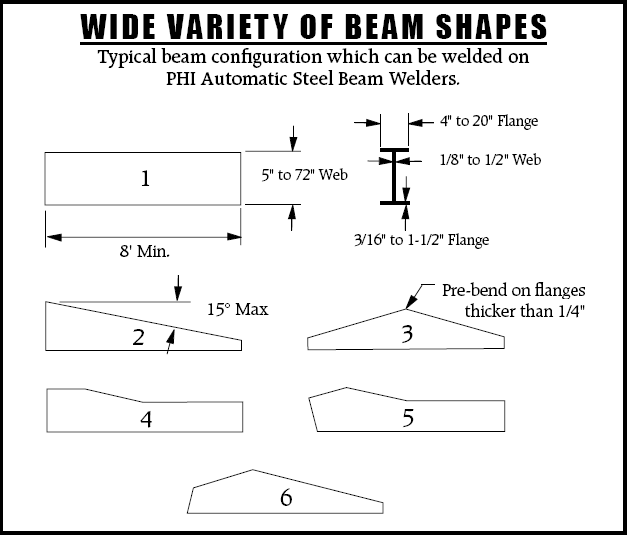
| Web Thickness: | 1/8” to 1/2” |
| Web Width: | 5” min. to 72” max. |
| Web Taper: | 15° max. |
| Flange Thickness: | 3/16” min. to 1-1/2” max. |
| Flange Width: | 4” min. to 20” max. |
| Beam Length: | 8 ft. min. |
| Beam Section: | 325 lbs./ft. max. |
| Beam Weight: | 12,000 lbs. overall, max. |
| Weld Fillet Size: | 1/8” min. to 5/16” max. |
| Welding Speed: | 20” to 120” per minute |
| Typical Welding Speed: |
|
Production Capacity
While actual production capacity will depend on the size and type of beams to be fabricated, typical output is 2,000 tons of steel per month in one eight-hour shift employing only three operators.
Options Available
Computer Control System
This option includes a computer-control system with touch-screen programming and operation. It utilizes an industrial PC and machine-interface software for user-friendly operation.
It features easily accessible diagnostics indicators, message display and custom graphics, including electrical and hydraulic schematics and functional diagrams. Program input can be made via touch screen or keyboard.
Welding programs may be downloaded remotely from a connected PC or network. It also includes a one-day data logger to provide a record of the machine operation.
Maximum Web Size Of 84”
This option allows for the manufacture of beams with maximum size of 84”, instead of the standard 72”. All elements of the system are modified to accommodate the larger web sizes.
Welding Heads For Manufacturing Crane Beams
A special welding head design is available for the manufacturer of crane beams. In crane beams, the top flange is a “C’ channel with the short sides directed inwards to the beam.
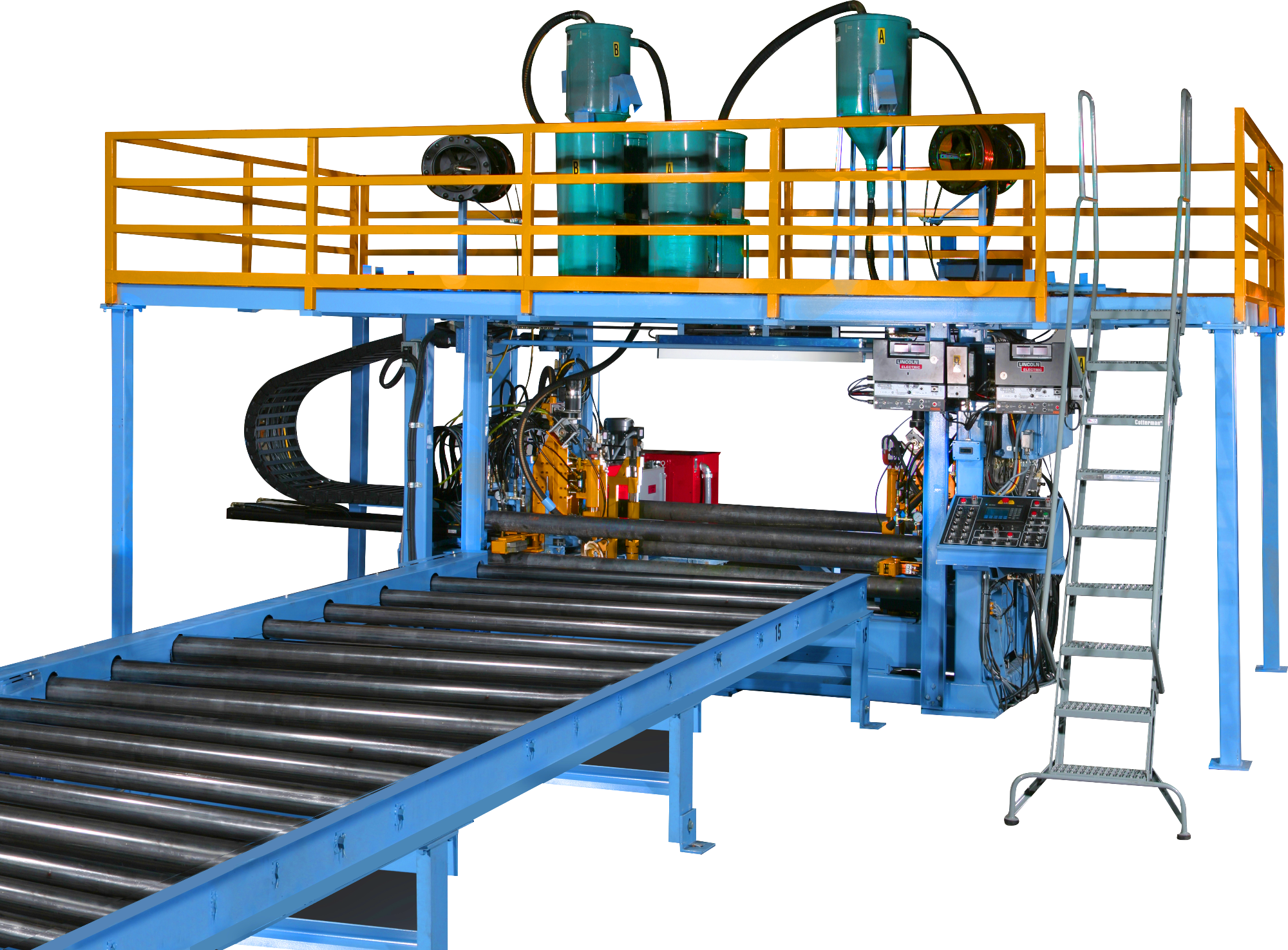
Mezzanine on Main Welder
This option includes a platform with rail guards and stairs for easy access. The platform is used for storage of flux and wire and allows room for the operator to load flux hopper, and change wire drums and reels.
Flange Tilting Assemblies
This option, when incorporated in the conveyors leading to the Tacking Fixture, allows the automatic tilting of flanges to a vertical position in preparation for beam pre-assembly. This system includes two flange tilting assemblies, one on each outbound side of the conveyors.
The Flange Tilting Assemblies can be opened to a position 37° from vertical or to a fully horizontal position depending on the material handling system used. If flanges are transferred by pushing from adjacent storage racks, the 37° open position is preferred. If flanges are transferred by means of a gantry type loader, the fully horizontal position is recommended.
The tilt assemblies utilize the tacking fixture’s hydraulic power unit. Controls are conveniently located at the tacking fixture control station.
Auxiliary Equipment for Welding Systems
Enhance the speed, ability, and productivity of your PHI Structural Beam Welding Lines by adding auxiliary equipment like PHI’s Flange Tilting Device and Beam Turning Device.
Videos
PHI Welders